
Sigh…editor’s note: I upgraded the KeyShot program and how it works. This changes the KeyShot package files that I reference throughout this website and I am working to get all the links straightened out. So if you see a KeyShot package file that you really want, be patient, I am working on it. I need to find them first, then upload the upgraded ksp file, then get all the links straight. pg
I have finally finished creating a video to show the walking motion of the robot. The video uses the Little Robot because it is simply technically easier to manipulate the postion of all the parts of this robot in a Sketchup drawing than to use the Pistonrobot.
I certainly imagine that people may wonder exactly how did I make a video of a robot that does not exist as a physically real object? The answer is that the video is not from a camera recording the robot as it moves. Instead I used Sketchup to make various poses or stances of the Little Robot, then I exported these poses to KeyShot and used KeyShot to render out images of these stances. Then I used a video editing program to “string together” these images into a video. This takes advantage of a feature of the human brain in that if a human is presented with a series of very similar images displayed in sequence rapidly enough, then a human brain will just “decide” that this collection of images is not a collection of images, but instead is a video of an activity.
Another question will be, “So, why bother to make this video?” One purpose is to answer one of the central tenants of the Pistonrobot project which is that the motion of a robot that is constructed with geometry much like that of a human and the robot is constrained to do physical activities that are much like these same activities as done by a human, then the piston related robot will “look” and “move” much more like a real human than is the motion seen from currently available electric motor, rotary motion type robots.
Another important objective of the video is to help in the creation of the power plant, or engine, or energy source that will give the robot its ability to be autonomous and still be able to move. At some point, if autonomy is desired, then there must be a place in the robot where an energy source that represents potential energy is converted into an item that can provide usable motive energy to the parts of the robot.
Specifically, for the Pistonrobot project, I have chosen carbon based petrochemicals to be the potential energy source and pressurized fluid (water) as the material that the robot uses to actually move itself.
Therefore, in order for the robot to have autonomy with respect to movement, then there must be a physically real place and device where there are separate inputs of liquid fuel (diesel fuel, or jet fuel) and water at low pressure into the device, and there is another place where there is separate outputs of pressurized water and the products of combustion of the fuel from the device. The pressurized water will flow around inside the robot to the various hydraulic cylinders of the robot on an as needed basis, and, in a loop configuration, the low pressure water that comes out of the hydraulic cylinders will travel back to the power device to be re-pressurized. The power device will take in fuel and air, burn the fuel via air-fuel combustion, use the heat of the combustion to pressurize the water, and vent the products of combustion back to the atmosphere.
It is certainly true that there are many other possible methods that could be used to give the robot autonomy with respect to robot motion. I have chosen the configuration described above for several reasons:
- In terms of having an “item” that the robot can “use” to get its various components to move, pressurized water has many advantages and these are discussed in other sections of this website.
- Petro-chemical based fuel as the end point source of energy is easily and widely available, and it is inexpensive to acquire and store. Issues associated with storage, transfer, control, ignition, and use of petro-chemical fuels are well known, well studied, and the solutions represent robust, available, and predictable technology.
- Petro-chemical based fuel as a potential source of energy for the robot to use on an as-needed basis represents a stable and dense energy supply material. Empty volume or “space” will be at a premium inside the robot and I want the robot to be able to “walk” all day long on one “fill-up” of its fuel tank. The energy density (with respect to energy available per volume of material) of petro-chemical fuel will give this “all-day” capability to the robot.
- The power source device of the robot must be quiet from a “noise” or “sound air-pressure disturbance” viewpoint. While it is clearly possible to create a robot that sounds like a lawn mower or go-kart, this amount of sound production will not be acceptable to almost all persons who would acquire the robot to use it for some purpose.
- The energy source for the robot must be robust, reliable, predictable, and non-dangerous to the actions of development of the robot. These development actions will include significant repetitions of starting and stopping the robot, starting and stopping the power source, removing and re-inserting both various parts of the robot, and various parts of the power source.
- Because of 5.) above, the use of exotic, expensive, or potentially unstable energy sources is unwise. In addition, power sources that have extensive legal, environmental, or governmental controls would be an unwise choice for “powering up” this particular type of robot.
Finally, after all that above, there still exists the question: “So why do you need to make a video?”
The purely technical answer is that from a math viewpoint, it is not “required” to have a video of the robot moving around in order to design a power source for the robot.
The problem that arises concerns the design of a power source for the robot that will allow the robot to do the types of moving around that you want the robot to do.
One can scale a power source way up in terms of just how much output it can give. Output here is used in the sense of just how much pressurized water per unit of time that the power source can supply. Issues associated with “scaling up” the power source include that increases of scale will increase the weight and physical space related size of the power source. Fuel consumption will go up, as will the need for more space in the robot somewhere to hold the large volume of this power source and additional space somewhere in the robot to hold the large volume of fuel that this scaled-up power source will need.
“Ok,” “No problem,” you may reply. “Let’s just scale down the maximum output parameters of the power source.” But the problem with arbitrarily scaling down the max output parameters of the power supply is that you could specify a power supply with so little max output, the the robot would not be able to physically do any of the actions that you want the robot to do.
Keeping the above in mind, let’s look at some specific issues. It is necessary to know the weight of the robot. The robot moves because the pressurized water sent to its hydraulic cylinders exerts a pressure on the surface of the pistons in the hydraulic cylinders. By multiplying the pressure of the fluid (pounds per square inch) times the area of the piston (square inches), one can determine how much force (pounds) that the hydraulic cylinder can deliver to its piston rod. In order to know that this amount of force supplied to the rod of the hydraulic cylinder is sufficient to move the robot, one must know how much resistance to motion the robot will apply against that rod. Basically, this resistance to motion will be simply the weight of the robot caused by gravity, as gravity pulls the weight of the robot down towards the ground.
We can get the weight of a part of the robot by simply listing out this part (in Sketchup), determining the volume of this part, and then multiplying this volume times the density of the material used to create this part. The total weight of the robot will be the total weight of all these parts. The total weight of all these parts will simply be the sum of adding all these individual weights together.
While the actual robot will probably need high strength materials like the duplex stainless steel alloys for some of the high strain parts, for the purposes of designing the power source of the robot, I will use the convention that all the parts of the robot are made of aluminum, so that to calculate the weight of any one part, I will just multiply the volume of that part times the density of aluminum.
In terms of the weight of the hydraulic cylinders, I will assume that each hydraulic cylinder will have a weight equal to the sum of (the weight of the aluminum parts of the hydraulic cylinder) plus (the weight of the fluid in the hydraulic cylinder, remembering that the fluid inside the cylinder is water).
In order to add in the weight of the fluid that is inside a hydraulic cylinder, we need to have a convention for determining how much fluid is present in the cylinder. I will use the following stipulations: First, the hydraulic cylinder set to its fully retracted state. Second, the volume of the fluid in the cylinder will be calculated as equal to the total volume of the cylinder minus the sum of (the volume of the piston in that cylinder) plus (the volume of the piston rod that is inside that cylinder).
In addition, I will use the convention that all the parts of the various sides of the robot have mirror image symmetry with each other. That means that whatever is the calculated weight of one leg and its attached foot will also be the calculated weight of the other leg and its attached foot.
There is another force calculation that arises which involves evaluating whether sufficient force is available to a rod so that the part to which the rod is attached can achieve an acceleration value that is equal to whatever acceleration value that was requested by the robot control programming. I am not going to address any of these force-acceleration issues because, in general, under the conditions of just walking along at a normal pace where a real human could just walk along with the robot, then there is not going to be a need to accelerate the movements of the parts of the robot sufficiently that acceleration related force calculations would be a limiting step. Gravity and weight related issues will be much more the limiting step in these force calculations.
If we know the weight of the robot, then we can apply that weight to the various structures of the robot. By using geometric considerations concerning the angles and proportions of how the hyrdraulic cylinders are connected to the various structural components of the robot, we can calculate the forces that will be required in order for the rods of the hydraulic cylinders of the robot to be able to move the structures of the robot against the weight of the robot.
Just a knowledge of force, however, does not allow us to make a power calculation. The weight and geometry of connection considerations above do allow us to know the following: What is the max pressure that the power source must be able to give to the water that the power source is pressurizing?
The next requirement for “sizing” the power source is to evaluate how much water will need to be moving around.
As the hydraulic cylinders move their pistons back and forth inside the cylinders, we can calculate what volume of water is needed to make these motions occur. In order for these calculations to be specific for our questions about the robot, we need to let the robot make the motions that are of interest to us.
One way to approach this is to begin with the robot just standing in a stable and un-moving stance. Then we will create a sequence of stances that sequentially move the robot through the motions that would constitute the robot walking along in a straight line on level ground.
Specifically, bring the right leg and right foot off of the ground, move the right leg and right foot forward, place the right foot on the ground, then lift the left leg and left foot off of the ground, move the left leg and left foot forward, place the left foot on the ground, lift the right leg and right foot off of the ground, and bring the right leg and foot forward until the robot was back into the stance that it had at the beginning.
Considering the above, then, if we wanted the robot to just walk forward in a straight line (providing that there were no obstacles, no changes in the terrain, no stumbles, no falling down episodes, etc.) then one would request that the robot would just cycle the above set of stances over and over.
We can measure the extent of retraction or extension of each of the piston rods for each of the hydraulic cylinders of the robot for each of these stances.
Let us say, for example, that this cycle of stances involved 20 separate stances.
Note: As I set out the example below, I will use the Stance numbering and Stance naming conventions that I used in the image files that I created that show the robot walking. For your information, in these image files, the robot starts its walking cycle on Stance 3A because 3A is a dynamic walking Stance. The Stance for the robot when it is completely stable and just standing there is Stance 1A. Stance 3A is a walking Stance. Stance 3A is not a stable just standing there balanced unmoving Stance like Stance 1A. To get the robot from stable (Stance 1A) to walking (Stance 3A), the robot moves through an intermediate Stance, (Stance 2A). This is why the walking sequence starts with Stance 3A.
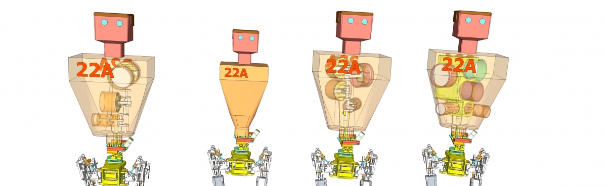
So for the specific example of the robot walking along in a straight line, then it will be cycling through its walking Stances. That is to say, for example, the robot begins at Stance 3A and cycles in order through Stances 4A, 5A, 6A, 7A, …., etc. up to Stance 22A and after Stance 22A the robot brings itself back to the configuration that it had in Stance 3A.
We can calculate how much fluid movement would be needed to change the robot between any of these Stances. Specifically, let us look at the Little Robot.
The Little Robot has mirror image symmetry between its right and left sides. What are the hydraulic cylinders of one side of the Little Robot?
One Hydraulic Cylinder for: Internal-Ext rotation Thigh
One Hydraulic Cylinder for: Adduction-Abduction thigh
Two Hydraulic Cylinders for: Flexion-Extension Thigh
Two Hydraulic Cylinders for: Flexion-Extension Knee
One Hydraulic Cylinder for: Dorsi-Plantar Flexion Ankle
One Hydraulic Cylinder for: Inversion-Eversion Ankle
One Hydraulic Cylinder for: Flexion-Extension Big Toe
One Hydraulic Cylinder for: Flexion-Ext Little Toe
One Hydraulic Cylinder for: Flexion-Extension Heel
Total Hydraulic Cylinders for each leg = 11
For our example, we will not be moving the toes or heels. Motion capabiliy for the toes and heels is present to allow the robot to have a way to compensate for small random variations in the terrain that it is walking upon so that it can walk by using the same major leg motion stances over and over without modifying these major stances even though the feet are encountering minor variabilities of the terrain that the robot is walking upon. I will discuss this issue of what the toe and heel motions are all about when I talk about balance. So, for this power unit set of calculations, we’ll just leave the toes and heels alone (unmoving).
Thus, for each Stance, we need to calculate how much fluid moved in each of the 8 Hydraulic Cylinders of the Right Leg and each of the 8 Hydraulic Cylinders of the Left Leg.
If we total up all these calculations, then we will know how much fluid motion was required to get the robot to cycle from Stance 3A through Stance 22A.
Surprisingly, this is still not quite enough to get what we need to make a proper sizing calculation. The power parameter for the power unit is power, not just energy or work. In order to bring the calculation up to a power calculation, we will need to know not only how much pressurization is required and how much volume of fluid will be needed to be pressurized, but we will also need to specify what amount of time will be needed for us to pressurize this volume of water.
This time calculation is not that difficult. We just need to specify how fast is the robot walking along? That is to say, we need a speed statement. I have chosen the robot to be basically either a companion or a helper (the robot will, for example, carry the supplies for a person as that person walks along) and I feel the correct specification for this initial sizing analysis for the power unit of the robot would be to let the robot just be walking along beside a person. This speed of walking is 3 miles per hour (mph).
To summarize: (We kept the robot at the size it has in the Sketchup drawings)
- We got the physical size of the robot
- We got the weight of the robot
- We got how much pressurization we would need
- We got the Stances needed for straight line walking
- We got the total fluid (volume) for one cycle of walking
- We set the speed of the robot
- The size of the robot gives us the length of the stride
- The speed of the robot gives us the strides per unit time
- Multiply Strides per unit time times volume per stride
- This gives us volume per unit time
- Multiply Volume per unit time times max pressurization
- This gives us a power value
So we now have a flow-pressurization parameter. That is, we know how much flow we need in volume per unit time and we know how much pressurization we need to put into that flow.
This allows us to design a power source with specific dimensions and capabilities.
And it allowed me to create a video. The parts of the video are the 22 Stances that comprise walking along in a straight line plus the Stances that show the robot changing the direction of its movement. While you may notice that the discussion above does not refer to the robot changing its direction of movement, I discovered that a video of the robot just walking forward in a straight line is not very compelling.
In addition, if one wanted the video to “cycle” where the robot began at a spot and moved along and then wound up back at that same spot to start the cycle again, well…
You can’t do that unless the robot changes its direction of movement. I decided that with respect to changes of motion, these can be categorized. The robot can turn left or turn right. The turning motion can be turning right with the big portion of the turning occurring with the right foot on the ground (Right turn off the Right foot, abbv: (R off R)), or turning Right with the big portion of the turning occurring with the Left foot on the ground (Right turn off the Left foot(R off L)). And the left turn has the same specifications. The result is that there are 4 types of turns (if we call Right turn off Right foot = (R off R),then the set is (R off R), (R off L), (L off L), (L off R).
To help lower confusion, I felt I needed some naming conventions for all of these different Stances. I called the Stances of straight line walking as just Robot 3A, Robot 4A, Robot 5A, etc., all the way up to Robot 22A.
I felt the naming convention for the Robot Stances of the turns should be different from what I had for straight line walking, so I used Parts instead. So, for example, if 9 Stances were needed to demonstrate the cycle of a Left turn off the Left foot, (L off L), then the 9 Stances of (L offL) would be named as follows:
Robot (L off L) Part 00,
Robot (L off L) Part 01, etc.,
all the way up to (L off L) Part 09.
Its my opinion that the renderings in KeyShot are just prettier to look at, so I sent the Sketchup drawings to KeyShot.
The parts of these renderings are as follows:
- the “Floor”, I made a floor with a specific pattern, and I added squares drawn in on the floor,so people could look at what is happening, the squares are 12 inches on a side. I also added little square markers to show where different sequences of Stances should begin and end their sequences. These little squares are labeled as Sets, and the Sets also have numbers in their labels.
- the “straight line walking”, this is a set of 20 Stances
- the “Right turn off Right foot”, or (R off R)
- the “Right turn off Left foot”, or (R off L)
- the “Left turn off Left foot”, or (L off L), and finally
- the “Left turn off Right foot”, or (L off R)
The way one makes the videos is to set up a KeyShot *.bip file with the floor present. Then, import, (for example) the straight line set of Stances, and place them on the floor at the Set marker where you want them to be. Then cycle them along by making only one Stance at a time to be visible, and then rendering an image.
If you want a turn to happen, then import the Stances of whatever turn interests you onto the Floor bip file as discussed above, move the Stances of the turn around until they are at the Set marker that you want, and again cycle them along and render images.
I discovered that to get it all to be at least reasonably seamless, it is necessary to add portions of the straight line walking Stances in front of and following the Stances of the turns. For example, you may need to have Stances 3A – 7A in front of the first Stance of (L off L), and then when the final Stance of (L off L) occurs, you may need to follow that Stance with 17A – 22A to get it back to where you can run another set of Stances.
So that you can “fool around” with this yourself, I have created 6 “Package Files” in KeyShot.
- a Package for “The Floor”
- a Package for “Straight line walking”
- a Package for “Left turn off Left Foot”
- a Package for “Left turn off Right Foot”
- a Package for “Right turn off Right Foot”
- a Package for “Right turn off Left Foot”
I have placed these Package files in my website area where you can do downloads. I rendered a separate image file for each of these Package downloads. This image file shows the various Stances of the package in their “real” configuration where they are really close together and basically “all over” each other. I added to this a group where I “spaced out” the Stances so they have some distance between each Stance so that you can see them better. But I will remind you that if you want to make videos, then you need to use the Stances that are packed up right on top of each other to get the correct effect. I think, probably, this will be more clear when you try it.
To get it to work, download the “Floor” package and open it in your copy of KeyShot. Then download a Package file for one of the sequences of walking and open it by itself in your copy of KeyShot. Then open your “Floor bip” file and ask it to import your “Walking Sequences bip file” and off you go.
Here’s an example KeyShot v8 package file that you can download, it is only about 2mb and it shows only the floor that the robots are walking on.
Download 2mb KeyShot Package file Floor only from v31 (1262 downloads )