It became clear that once we had the robot put together into a structure that could stand and move and walk, then we would need to work through the issues of what kind of power source would the robot need.
It is right at the very beginning of our starting any power discussion for moving a physical object, especially if the object will be overcoming the constraints of motion that gravity will place on the object…. that we will be simply forced to evaluate “What is the weight of the Little Robot?”
As I explain below how I did this, I will just add some of the images that are used in the presentation of the weight of the robot. I am basically just putting them in here and there. The whole set of these images are available here at the website both as a Slideshow presentation
Slideshow – Weight of the Little Robot
and as an image collection where one can download the full sized image files.
Downloadable Images – Weight of the Little Robot
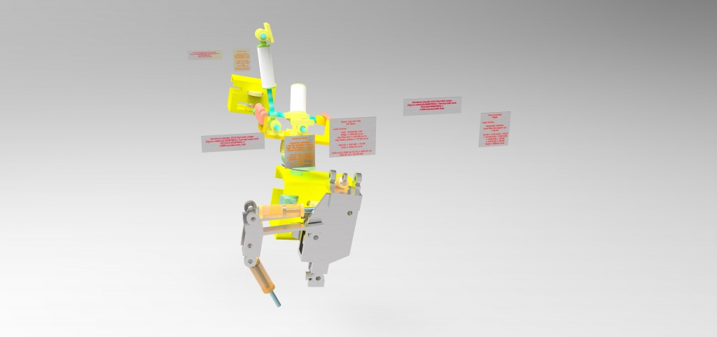
What follows here is an extremely magnified image which is a crop from just a tiny portion of the drawing that shows all the parts. In order for it to be where the data can be read on the website, this amount of magnification is needed. I am working to upload some more of these extremely magnified images so that you can see on the website what it would look like if you just “scrolled around” in the main drawing file.
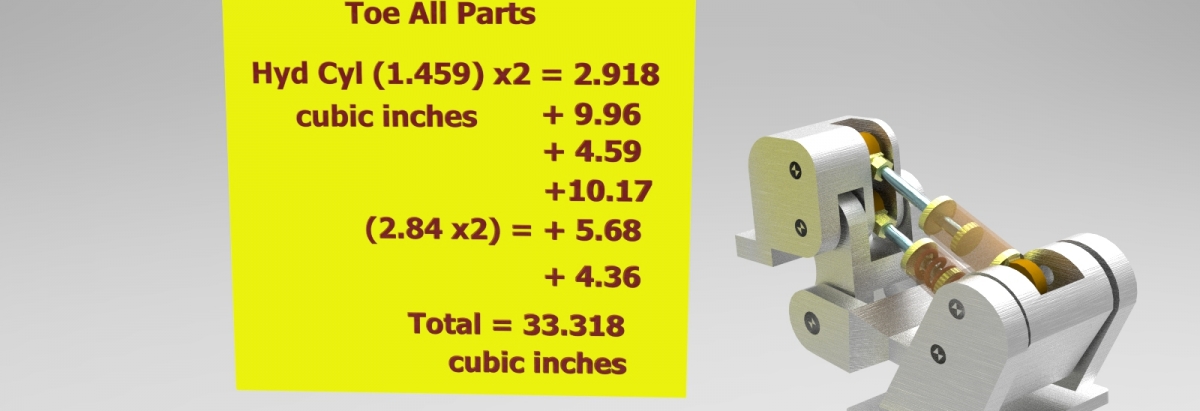
We can take the toe itself and break it further down into a collection of parts. These parts include two types of hydraulic piston type structures that are a present in each of the two toes and also in each heel. One structure is purely nothing more than a hydraulic piston. This hydraulic piston is used to raise and lower the resting position of the toe when there is no weight on the toe. There other piston structure present in each toe and each heel is has a physical form like a hydraulic piston except that hydraulic fluid under pressure is not present inside the cylinder to move the piston head, instead there are 2 die springs inside the cylinder with the piston head located in between these two springs. The effect of this is that as a force pushes the toe upward (for example, as the weight of the robot is placed onto the toe) then one die spring is compressed by the piston head and this die spring acts as a spring-based shock absorbing device to shield the rest of the parts of the robot from shock loads. If the toe was pulled downward (for example, the robot “stumbles” over an obstruction that it did not notice), then as this downward force was transmitted to the toe, then the other die spring would be compressed by the piston head, and again this spring would also act to shield shock loads from forces applied to the toe in this other direction. I can perform an extreme magnification of this one section of the robot with these parts separated away from each other, and these magnifications follow. The first is showing the hydraulic cylinder of each toe and each heel that is used to set the “resting position” of the toe or heel.
File type: JPG
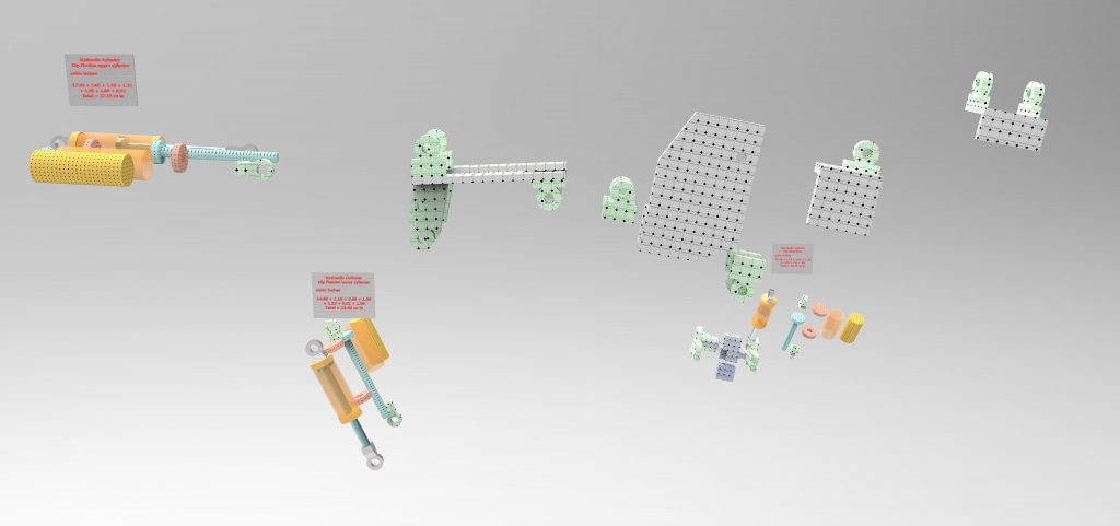
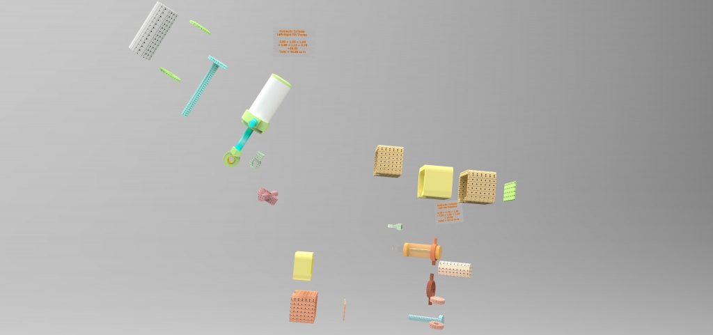
The next images are extreme magnifications of the structural parts of each toe or heel that allow the toe or heel to have their desired action. I separated them apart so you can see them more clearly, and then I tried to “ease” them back together, which looks OK, but the re-assembly is not perfect because re-aligning parts that one took apart is not as easy as you may think. But the re-assembly is good enough for you to see how the parts related to each other.

I could do the process above for all of the parts of the robot, but that would just be too time consuming.
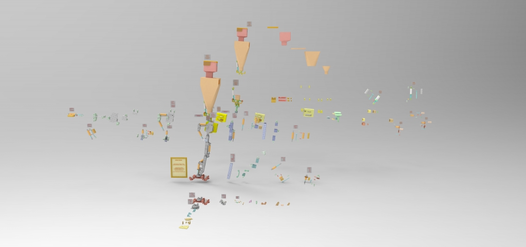
This image below is what the main drawing image file looks like if I upload a version of it that allows one to see all the parts that are in the entire collection. The magnified image crop above is showing just the poster that is displayed in this image below.
Since the robot was designed in a 3D drawing program, then it is not that difficult to request this 3D drawing program to “view” the Robot as a collection of single parts, and then to ask the program to “focus down” on one single part, and then ask the program to display the volume of that one part. This process can be done for each individual part in the robot.The Sketchup drawing file that created the image above can be downloaded. When this drawing file is opened by Sketchup, the various parts and sub-assemblies shown in the image above can be expanded and enlarged by huge margins. There is enough enlargement available by using Sketchup to view this file that the exact cubic inches volume data of every object can be seen clearly.
The Sketchup drawing file is listed below. The filesize is 46 megabytes, it has a .skb extension, and it is a Sketchup 2016 drawing file.
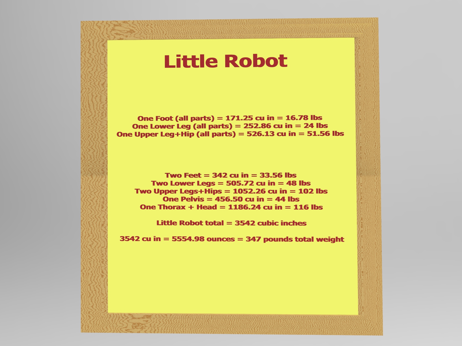
Once we know the volume of the object, and we can assign to the object what is the material of its construction, then it is a simple process to take the volume of the object and multiply that volume times the density of the material that was used to make the object. This will give the weight of that object.
The total weight of the robot becomes simply the result of adding together the weights of all the parts that are present in the robot.
Unfortunately, we gave a lot of movement capability to the robot and for a structure that is a collection of individual parts, each additional movement capability that is given to the final structure is done by adding more parts to the structure. This means that if we gave a lot of movement capability to the final structure, then it is going to have a lot of individual parts!
From a presentation viewpoint, it is difficult to coherently present a large collection of smallish parts. There just gets to be so much “stuff” in the image, that nothing can really be shown very clearly.
The traditional solution to this is just breaking the main structure down into its parts and showing them one by one. This is really a boring way to show off a structure.
It struck me that I could break the main robot structure down into sub-structures where these sub-structures had much fewer individual parts. Then the image of the sub-structure could be enlarged so that people could look at the individual parts, but still be able to visualize how they all went together.
I realized that most people will all have slightly different manners of putting the robot and its parts into their own conceptualization system inside their own head. I didn’t really want to force viewpoints.
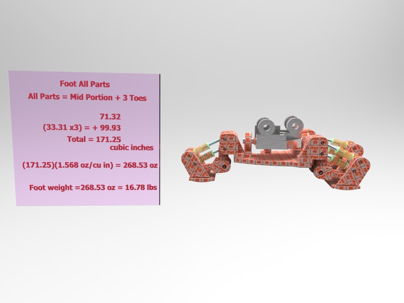
I realized that the drawing program will allow an individualized texture can be applied to individual parts in a manner where that texture basically “paints” the whole part, and the paint includes the numbers that are the volume (in cubic inches) of the part.
The advantage of this is that whichever way a person chose to look at the part (from above, from below, close-up, far away, from the left, from the right, etc.), that all these views would still include a presentation of the volume of the part.
I thought that was cool.
From a mechanics of presentation viewpoint, there is a “big overall viewpoint” image that shows the whole robot and how all the parts go together. This image is so large that specific data about specific individual parts will not be displayed in a readable manner because it just takes too much magnification to get that kind of detail for individual parts.
But you can use the “big overall viewpoint” image to see where sub-structures are located in the robot. Then you can go to images of these sub-structures, and when these images are enlarged, one can see data about individual parts.
So that’s how this section works. Just look around in the images for whatever interests you.
I should note that they are not small images from a megabyte level, and the website programming compresses them and “wrecks” useful magnification.
I placed all the images in a downloadable image collection where you can pull the real images down into your computer and enlarge them with a reasonably good image program. Then you will be able to see the details.
Finally, I thought this was pretty neat, but, then I think almost anything about the robot is fun to learn.
If your interest on this topic is just to get to the end of it, well
The Little Robot (providing its parts are all made of aluminum or aluminum alloys), then
The Little Robot (in its entirety) weighs 350 lbs.